
Voltaic designs and manufactures custom, high-quality solar power panels and mounting solutions for a wide range of industrial applications including asset tracking, livestock tracking, agriculture, environmental monitoring and parking. We work with you to understand your dimensional, power and other requirements, translate those into technical drawings, test for performance within your design, and manage the supply chain and import process.
Custom Solar Panel Design Process and Options
- Development Process
- Qualification and Performance Standards
- Power and Voltage Options
- Coating Options
- Substrate Options
- Cell Stringing vs SMT
- Solder Pad, Wire and Strain Relief Specifications
- Mounting Options
- Design and Tooling Fees
- Minimum Order Quantities
- Supply Chain and Tariffs
- Solar Panel Design Tips
- Request a Custom Quote
Our team typically follows a four-step development process:
2. Panel Specifications and Design - We produce one or more panel drawings that include dimensions, material, voltage, power, materials, wiring, and mounting mechanism.
3. Samples - We produce samples for qualification. There are a range of tests to validate for performance and durability against your specifications.
4. Full Production - Panels are produced at scale. We manage QA and the import process or shipment to your CM.
Our panels have been thoroughly qualified. In most cases the material stack that we use for your panel has passed:
- Accelerated age testing (combined heat, humidity and UV)
- Thermal cycling (TC50)
- Damp Heat (DH1000)
- Mechanical Shock and Vibration
- Impact
- Exposure to salt water, chemicals and oils
Talk with a Voltaic representative to get specific details.
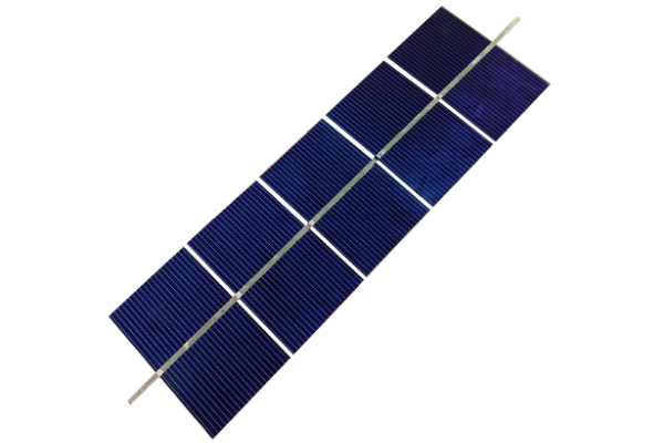
^back to topTotal power is determined by surface area and solar cell efficiency. We most frequently use both standard monocrystalline cells and SunPower back contact cells.

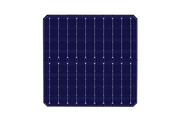
We cut laser cut those cells into smaller, equal-sized pieces and assemble them into a panel. The more cell area, the more power is produced.
| Example Cell | Cell Type | Dimensions (mm) | Total Power (Watts) | Power per cm^2 (Watts) |
|---|---|---|---|---|
| EEPV 21.2% 5 Busbar Cell | Monocrystalline | 156 x 156 | 5.18 | 0.0212 |
| 23.1% 10 Busbar Cell | Monocrystalline | 182 x 182 | 7.59 | 0.0231 |
| SunPower 23.1% Maxeon Gen III | Mono IBC Back Contact | 125 x 125 | 3.54 | 0.0231 |
| SunPower 23.9% Maxeon Gen 6 | Mono IBC Back Contact | 166 x 166 | 6.54 | 0.0239 |
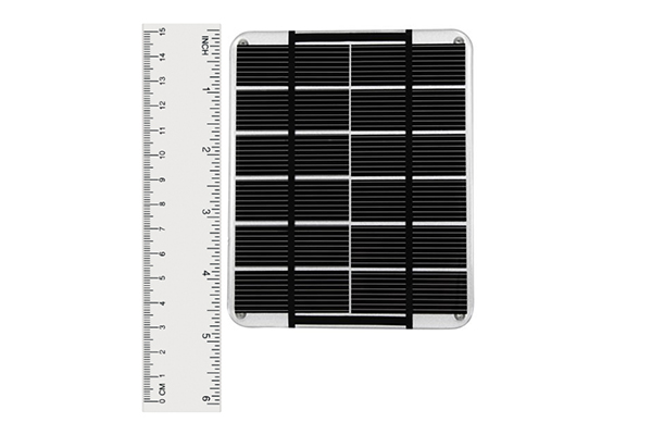
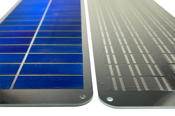
For example, this monocrystalline panel on the left has 118 cm^2 of cell area (12 52mm x 19mm pieces) using 19.1% efficient cells and is rated for 2.3 Watts. The SunPower panel on the right has 129 cm of cell area (18 50mm x 14.4mm pieces) using 23.1% efficient cells and is rated for 3.0 Watts.

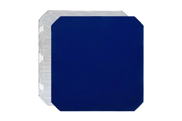
SunPower cells gain much of their efficiency by moving their tracer lines and connection points to the back of the cells. While more expensive on a per Watt basis, SunPower cells (vs. traditional monocrystalline cells) have:
- Higher efficiency - roughly 15% additional power per unit area
- Strong copper connections maintain power even if a cell is cracked
- Fewer constraints to cell size and layout when using an SMT production process
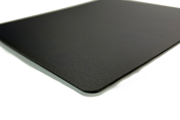
- Even appearance can disappear on a matte black background
- Slightly more physical flexibility
The downside of SunPower cells is that they cost more on a per Watt basis than traditional monocrystalline cells. On larger panels, there are also more constraints on how the cells can be cut. SunPower are available with ETFE or glass.
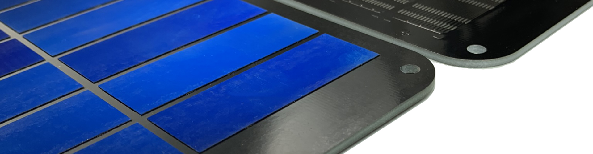
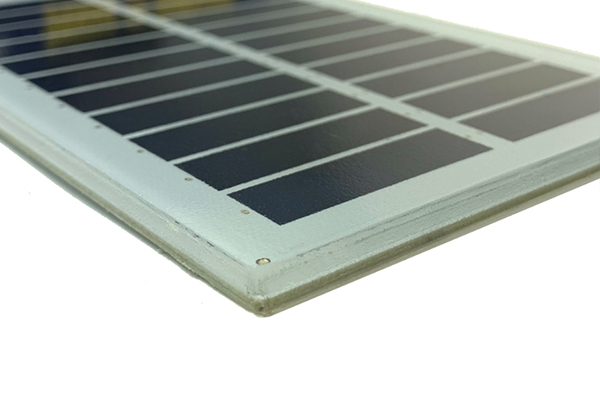
Panels made with traditional monocrystalline or SunPower cells can be laminated with glass or ETFE.
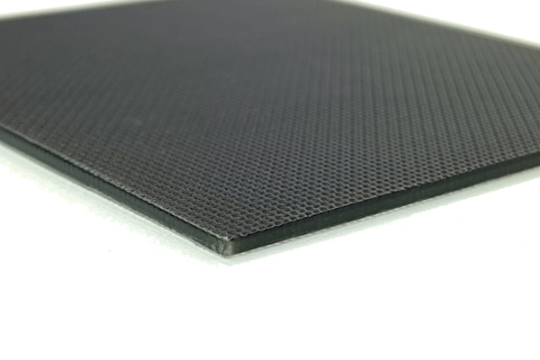
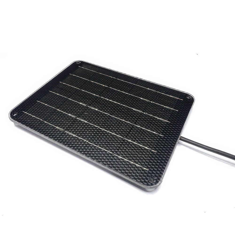 10BB cells with ETFE lamination
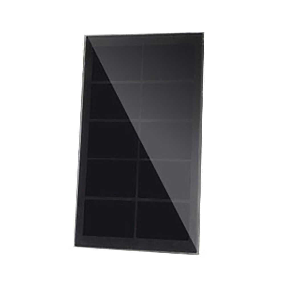 SunPower SMT construction with glass lamination
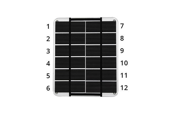
We create a specific voltage by stringing individual cell pieces in series. Each cell piece is ~0.55 Volts (0.58 - 0.59 for SunPower), so for the 2.2W panel shown below, we used 12 pieces to create a 6 Volt panel.
Where possible, we recommend producing as low a voltage panel that works for your circuit. Here are some of the advantages of a lower voltage panel:
- Higher current - In the same area, an 18V panel will produce less current than a 16V panel. Your circuit may waste that excess voltage leaving you with 12.5% less power.
- Higher power - Each cell requires a gap between the next cell. The more cells on a panel, the more area is wasted to the gaps between cells.
- More partial shading and fouling risk - If an object adheres to or partially shades the panel, the power loss will be greater on a higher voltage panel. A string of cells generates as much current as the worst performer in the string. When cell pieces are smaller, the shading impact increase.
- Slightly more expensive to manufacture - more pieces equates to more labor
^back to top
We recommend a coating for the panel based on your durability, cost, and design constraints. The four options are:
Glass: Great UV resistance and combined with a frame, a glass panel can have the longest lifetime. Glass panels are the heaviest on a per Watt basis.
Urethane: Highly UV resistant and durable. Our urethane solar panels last up to 10 years in the sun with minimal power degradation. The urethane coating is poured or "potted" on the solar cells and leads to a highly waterproof panel. Each individual cell is completely encapsulated by the urethane.
Epoxy or PET: Panels made with these coatings will be inexpensive, but we don't recommend this coating for most industrial applications as it tends to have a relatively short lifetime. They are the least UV resistant of any of the options.

From Left: ETFE, Glass, Glass in Frame, Urethane PET
| Coating | Expected Lifetime Outdoors (Years)* | Typical Thickness (mm) | Approximate Weight of 5 Watt Panel (kg) | SMT Available |
|---|---|---|---|---|
| ETFE | 7+ | 2.5-3.5 | 0.21 | Yes |
| Glass | 10+ | 5 | 0.37 | Yes |
| Glass with Frame | 15+ | 20 | 0.49 | Yes |
| Urethane | 10+ | 5 | 0.25 | No |
| PET | 2-3 | 2.5-3.5 | 0.21 | Yes |
*Lifetime will vary based on a wide range of factors including panel design, materials used, production process, physical environment and other operating conditions.
^back to topThe solar cells are mounted on a substrate or backing. Again, there are several options.
PCB: Different thicknesses available, from 0.6mm to 3mm depending on requirements. This is our most common material and can be single sided, double-sided or contain no copper at all (we call this simply FR4).
KPF: No rigidity, but is paired with glass panels as the glass provides the structural support.
Aluminum-Plastic-Aluminum: Only used in our urethane panels. Very high strength to weight ratio material used in commercial building applications. Allows embedding of screw or nut into substrate.
^back to topThere are two ways we connect the cell pieces in series.
The more traditional way is to solder the positive of one cell piece to the negative of the next cell piece with a ribbon. This is usually done with a stringing machine. One or more strings are then placed on the substrate and connected as needed.
The SMT method starts with a PCB that matches the back contacts of SunPower cell pieces. Cell pieces are placed onto the PCB by a modified SMT machine normally used for pick and place of components. The PCB and cells are sent through a reflow oven to solidify the connection prior to lamination.
SMT provides more flexibility on cell layout and size and is our preference when making 1 Watt or less panels.
^back to topIn addition to customizing the embedded screws or adding through holes, we offer the ability to create a custom panel mount for your specifications. This includes the design and manufacture of custom brackets, gaskets or VHB seals.

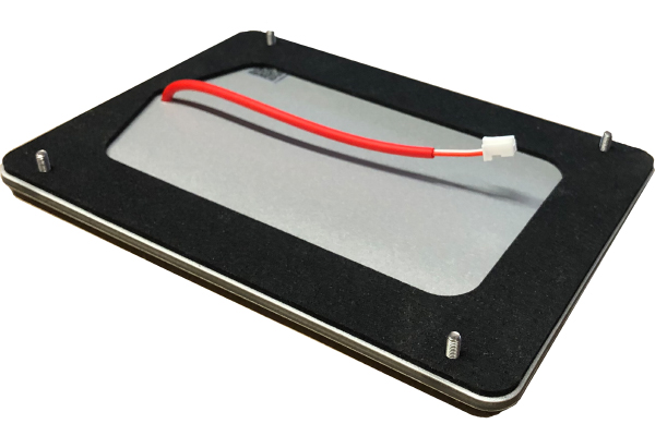
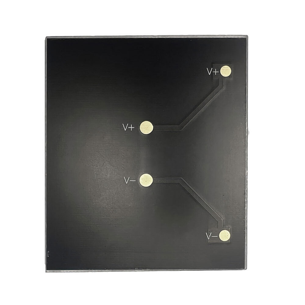
When we use a double sided PCB pads can be placed virtually anywhere on the back of the PCB. Pads can be ENIG.
Wires can be virtually any length, diameter and connector type. If the connector is outdoors, overmolding may be required to make it waterproof.
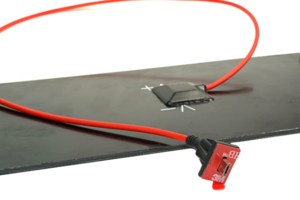
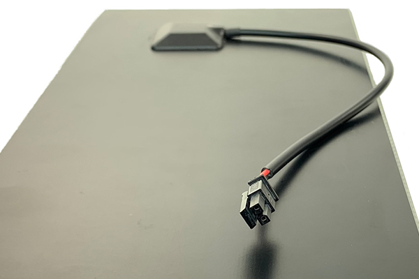
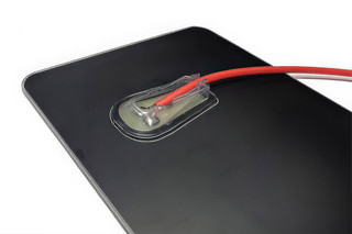
On the back of our ETFE panels, we normally cover the connection to the wire with silicone sealant and a junction box. This combination provides both waterproofing and strain relief. We can use VHB or a dab of silicone to provide strain relief.
There are no design fees to create a drawing of your custom solar panel. Most panel designs do not require tooling fees. The exception is for overmolding or a custom injection molded part.
^back to topOur MOQ is 500 - 3,000 units depending on the size of the panel.
^back to topWe think about the panel import process from the very beginning of the design process by selecting solar cells and manufacturing locations to minimize applicable tariffs.
Solar panels brought into the United States are subject to a wide range of countervailing and anti-dumping duties. If not managed properly, duties on panels can exceed 285%. We manage that risk for our US customers, by importing and clearing panels prior to delivery.
For customers assembling the product at a CM, we work with you to make sure the panel and solar cell production location aligns with your import strategy.
^back to top- Estimate your realistic solar power production in worst-case scenarios. Here's how to estimate solar irradiance by month based on your expected location(s).
- Reduce your device’s power requirements before discussing the panel’s power requirement. For example, if you can reduce your device’s power requirements by 50% this reduces the size of the solar panel by 50%, saving you money, size, and weight.
- Prototype your project with off the shelf small solar panels before moving forward with custom designs. This allows you to confirm the efficiency of the circuit and power production estimates before investing in a custom design.
^back to top