Charge Controller RS-485 Guide
The charge controllers in the Voltaic’s integrated solar systems come in two versions: a 10A version for the 18Ah battery (V102) and a 15A version for the 60/100Ah batteries (V107, V112). Both versions have a 4-pin output cable for RS-485 ModBus RTU half-duplex communication.
This document will outline the hex codes and firmware formatting and procedures to read data from and configure the controllers, using that 4-pin connection. This document may be updated in the future to accommodate new info and customer feedback.
The RS-485 Modbus feed of the charge controllers is output through a 4-pin female M8 connector. The feed is limited to 2 serial pins (A, B), so the feed is only half-duplex (cannot transmit and receive data simultaneously).
Important Update
We’ve updated the wiring of our M8 extension cables for RS-485 communication to improve consistency and compatibility across our battery and device connections.
In the old version, the RS-485 A and B signals were reversed:
Old: Pin 3 = B, Pin 4 = A
New: Pin 3 = A, Pin 4 = B
If you're connecting a new cable to an older system, make sure to double-check pin assignments, especially for RS-485 communication lines. Miswiring A and B may cause devices not to communicate properly.
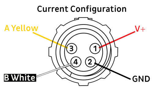
Current Configuration
| Pin Number: | Pin Name | Pin Description |
|---|---|---|
| 1 | V+ Red | Unregulated 12V battery voltage |
| 2 | GND Black | Ground |
| 3 | A Yellow | Half-duplex RS-485 serial pin |
| 4 | B White | Half-duplex RS-485 serial pin |

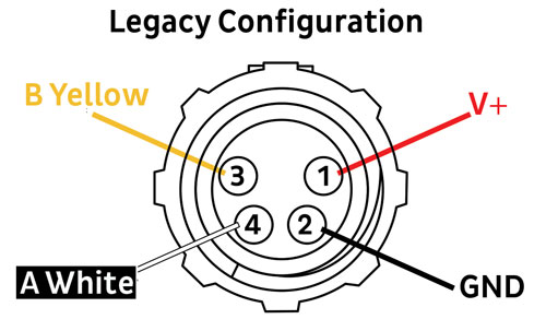
Legacy Configuration
| Pin Number: | Pin Name | Pin Description |
|---|---|---|
| 1 | V+ Red | Unregulated 12V battery voltage |
| 2 | GND Black | Ground |
| 3 | B Yellow | Half-duplex RS-485 serial pin |
| 4 | A White | Half-duplex RS-485 serial pin |

If the device reading RS-485 data has its own power source, it’s not necessary to connect to the V+ pin.
Because the RS-485 serial feed depends on relative voltages, the RS-485 GND pin should be connected to the reading device’s ground.
RS-485 is a serial hardware format, so if the RS-485 feed is being routed to a microcontroller or other UART device it will need to go through an adapter IC. These adapter ICs sometimes require a HI/LOW pin to switch between transmitting and receiving.
The charge controller uses standard Modbus RTU protocol. This protocol depends on a few key communication parameters, shown below:
- 9600 baud rate
- 8 data bits
- 1 stop bit
- No parity bit
- No flow control
These parameters are crucial to successful RS-485 operation and can be configured in whichever Modbus library is being used.
Hex Format
The charge controller operates with a call-and-response protocol between primary/secondary devices in hexadecimal format. The formatting of the hex code is described with an example below:
Call
The following hex is a call to read the charge controller register that contains the Battery Voltage Level. A register is defined as 2 pairs of hex values (AB CD).
01 04 30 A0 00 01 XX XX
| Call | |
|---|---|
| 01 | The charge controller device ID. Default is 01 (can be changed on the device.) |
| 04 | The Modbus function code. 04 is for reading an input register. |
| 30 A0 | The register to be read or written. A list of relevant registers is included in the next section. |
| 00 01 | The number of registers to be read, for most cases this will be 1. |
| XX XX | Cyclic Redundancy Check (CRC). Data check to confirm successful communication. Autogenerated by many Modbus libraries. |
Response
The charge controller’s response to the call above would look something like this:
01 04 30 A0 00 01 XX XX
| Response | |
|---|---|
| 01 | The charge controller device ID. Default is 01 (unless changed on the device.) |
| 04 | The Modbus function code. 04 is for reading an input register. |
| 00 02 | The number of data bytes being returned. Twice the number of registers. |
| 05 46 | The value of the data register being read. Many register values are stored at 100x their true decimal value. In this case, 05 46 translates to 1350 in decimal, which means the Battery Voltage level is 13.5V. If a battery parameter is negative, it will be sent as a positive hex ID, with the negative value subtracted from the maximum register value (0xFFFF or 65535 or 655.35). For example, if the battery current is -2A (negative meaning leaving the battery), the reported decimal value will be 65335 (65535 - 200 or 655.35 - 2). |
| XX XX | Cyclical Redundancy Check (CRC) reply. Data check to confirm successful communication. Auto-checked by many Modbus libraries. |
| Modbus Function Codes | |
|---|---|
| 0x02 | Read Discrete Inputs |
| 0x03 | Read Holding Registers |
| 0x04 | Read Input Registers |
| 0x05 | Write Single Coil |
| 0x06 | Write Single Hold Register |
| 0x10 | Write Multiple Hold Registers |
Read Only Registers
These registers hold the real time measurements of the charge controller. These values cannot be written or altered via RS-485. Every value has a x100 multiplier that must be accounted for.
| Register Name | Function Code | Register Code | Decimal Code | Multiplier* |
|---|---|---|---|---|
| Battery Voltage Level (V) | 0x04 | 0x30A0 | 12448 | 100 V |
| Battery Current (A)** | 0x04 | 0x3047 | 12359 | 100 A |
| System Input Voltage (V) | 0x04 | 0x304E | 12366 | 100 V |
| System Input Current (A) | 0x04 | 0x304F | 12367 | 100 A |
| Load Voltage (V) | 0x04 | 0x304A | 12362 | 100 V |
| Load Current (A) | 0x04 | 0x304B | 12363 | 100 A |
| Environment Temp. | 0x04 | 0x30A2 | 12450 | 100 °C |
| Controller Temp | 0x04 | 0x3037 | 12343 | 100 °C |
| Battery Status | 0x04 | 0x3033 | 12339 |
** Signed Value - Decimal values from 0-32767 are positive. Decimal values from 32768-65535 are negative, where 65535 is -1, 65534 is -2, etc.
Reading Battery Status
Battery temperature and voltage status can be read from register 0x3033. The read value must be converted to hex and split apart for interpretation. The first 2 hex digits correspond to over temperature protection, and the last 4 correspond to voltage protections:
| First Two Digits: | 0 - Normal 1 - High Temp. Protection |
Last Two Digits: | 0 - Normal 1 - Over Voltage Protection 2 - Low Voltage 3 - Low Voltage Protection |
For example, if you received the following reading:
00 | 03
The first two digits correspond to normal temperature function, and the last two to low voltage protection.
Read/Write Registers
These registers can be read to check charge controller settings, or written to alter charge controller behavior.
| Register Function | Function Code | Hex Value | Dec. Value | Data |
|---|---|---|---|---|
| Battery Output Switch | 0x05 | 0 | 0 | 1 - Turn on output state 0 - Turn off output state |
| Device ID | 0x03 0x06 |
0x9020 | 36896 | Default - 1 (Range 1-247) Use Function Code 03 to read current ID Use Function Code 06 to set ID to new value |
The easiest way to write a script to send and receive data over RS-485 is by using a designated Modbus library.
When using Python from a desktop computer, minimalmodbus is a straightforward and robust library for RS-485 communication. Below is an example of using minimalmodbus to read from and write to the charge controller. An RS-485 USB adapter is needed to communicate with the controller.
import minimalmodbus
import serial


instrument = minimalmodbus.Instrument(‘COM12’,1) # COM number will change depending on computer and port used


instrument.serial.baudrate = 9600 			# Sets the baud rate
instrument.serial.bytesize = 8				# Sets the byte size
instrument.serial.parity = serial.PARITY_NONE		# Specifies no parity bit
instrument.serial.stopbits = 1				# Specifies 1 stop bit
instrument.serial.timeout = 1				# Sets timeout value
instrument.mode = minimalmodbus.MODE_RTU	# Specifies the protocol


reg = instrument.read_register(36898,0,3) # Reads low voltage register value
# Arguments are: decimal register, number of decimals in data, function code
print("Low Voltage Protection: ", reg/100)


reg = instrument.write_bit(0,1,5) # Writes load output value to ON
# Arguments are: decimal register, value to store, num of decimals, function code,
# and whether the data is signed/unsigned
if reg == None:
	print(“Write Success”)
When using C++ on an Arduino compatible microcontroller, ModbusMaster is a good option. Below is an example of using ModbusMaster to read from and write to the charge controller. This script assumes an RS-485 adapter is being used that requires a pin to signal whether it should be sending or receiving data (pin 13).
#include
#include    // import necessary libraries
#define Battery_Voltage_Address 0x30A0 // Register we want to read
#define MAX485_DE      D13    // Send/receive signal
#define usbSerial Serial
ModbusMaster node;      // instantiate ModbusMaster object
double load = 1;        // Setting load output to ON


void preTransmission1()   // Sets pre-transmission signal (trans)
{
  digitalWrite(MAX485_DE, 1);
}


void postTransmission1()    // Sets post-transmission signal (rec)
{
  digitalWrite(MAX485_DE, 0);
}


void setLoad(){       // Turns controller output ON/OFF
    if (load == 1){
    Serial.println("Output ON");
    node.writeSingleCoil(0x0000, 1); // Write the value to the register
    delay(1000);
  }
  else{
    Serial.println("Output OFF");
    node.writeSingleCoil(0x0000, 0);
    delay(1000);
  }
}


int readModbusRegister(uint16_t regAddress)
{
  uint8_t result;
  uint16_t data;
  int value = -1;
  int numRead = 1;


  Serial.print("Reading Modbus Register at address: 0x");
  Serial.println(regAddress, HEX);


  result = node.readInputRegisters(regAddress, numRead); // Read register


  if (result == node.ku8MBSuccess) {    // Check for success
    Serial.print("   Response Bytes: ");
    for (uint8_t i = 0; i < numRead; i++) {
      Serial.print(node.getResponseBuffer(i), HEX);
      Serial.print(" ");
    }
    Serial.println();


    for (uint8_t i = 0; i < numRead; i++) {
    }
    data = node.getResponseBuffer(0);
    value = data;


  } else {              // Else error
    Serial.print("Error reading input register " + String(regAddress) +  ". Error code: ");
    Serial.println(result, HEX);
  }


  delay(1000);
  return value;           // return register value
}


void setup()
{
  pinMode(MAX485_DE, OUTPUT);   // Set pin modes and values
  digitalWrite(MAX485_DE, 0);


  Serial.begin(9600);       // Begin serial communication
  Serial1.begin(9600);
  node.begin(1, Serial1);     // Modbus slave ID 1, Serial1


  // Callbacks allow us to configure the RS-485 transceiver correctly
  node.preTransmission(preTransmission1);
  node.postTransmission(postTransmission1);
}


void loop()
{ int res = 0;
  res = readModbusRegister(Battery_Voltage_Address); // Read/print address
  delay(1*60*1000);           // Wait 5 mins
}
The scripts included above are also available standalone by request.
